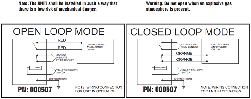
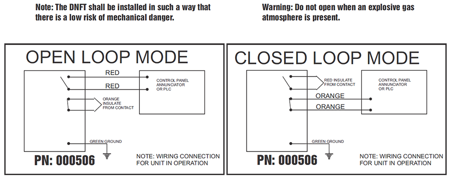
Dnft No-flow Wiring Diagram
The Revolutionary Digital No-Flow Timer for Compressor Lube Systems DNFT performs monitoring and shutdown functions like No-Flow Low-Flow or Excessive-Flow for Divider-Block Lubrication Systems. The following schematic shows a typical circuit diagram of the mass air flow maf sensor system.
Dnft Prg P N 000518 Digital No Flow Timer Dnft Digital No Flow Timer For Compressor Lube Systems Whitlock Instrument Dnft Whitlock Noflo Whitlock Instrument Dnft 000518 Prg Timer Model Number
Specification Proximity Switch DNFT Programmable DNFT Shutdown Signal NO YES YES Proximity Signal YES YES YES Local Cycle Indicator Separate Indicator YES.

Dnft no-flow wiring diagram. Digital No-Flow Timer DNFT. Maf sensor gets power from the pcm power relay red wire. Should read less than 10 in operation and open loop in alarm.
Single pole may sound simple but there are different ways to wire a single pole switch. How to wire fuel gauge and sending unit complete explanation. Otherwise the structure wont function as it ought to be.
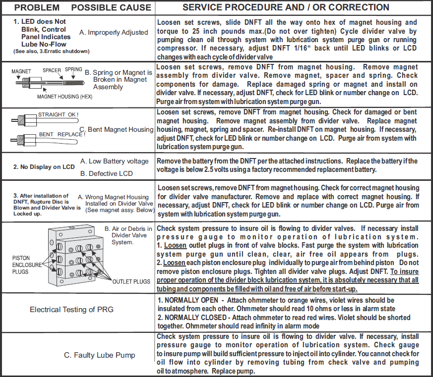
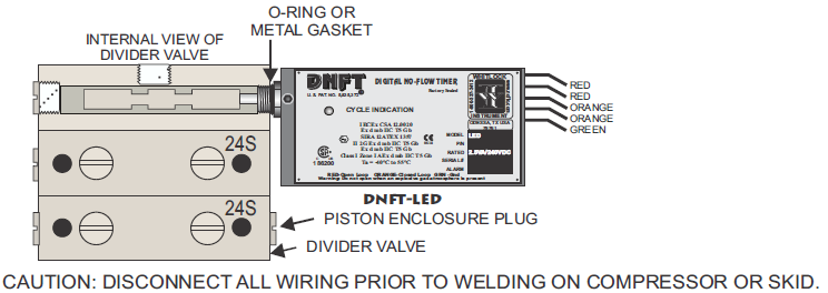
Presented using advanced software cg animation technology to help you understand. Will shut down the compressor preventing damage to cylinders pistons rods and packing. Normally Open - Attach ohmmeter to red wires.
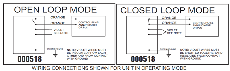
Wiring diagrams that accompany ariel dnfts present a visual representation of how to successfully connect your digital no flow timer. Flow Switch manufacturer defines opposite way No Flow. Each component ought to be set and linked to different parts in particular way.
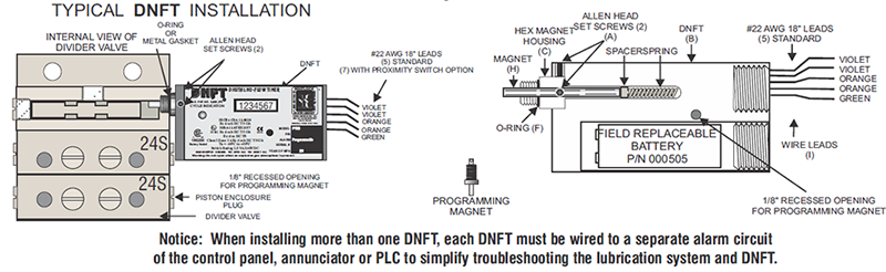
When more than one dnft is installed on the compressor or engine each dnft must be wired to a sepafwe alarm circuit on the control panel annunciator or plc to simplify troublshooting the wbrication system and dnft. This circuit originates from the breaker box containing a 2-pole 30 Amp breaker. 11086 vus male trinary switch.
I need the wiring diagram for the mass air flow sensor to a 2006 mustang gt. The 3 prong dryer wiring diagram here shows the proper connections for both ends of the circuit. I believe that is the correct wiring diagram.
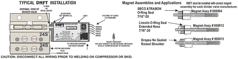
Additional wiring information is available in er 5607 including how to properly ground your dnft a potential source for dnft headaches that is easily prevented. Monitors each cycle of a divider block system. Faulty wiring from DNFT to control panel or air in system see above for air in system.
There are several connection points on ENTRON Controls where a WFS can be connected to indicate a water flow problem and effect the operation of the control. The gauge of a piece of wire refers to its diameter. Mass Air Flow Wiring Diagram bosch mass air flow sensor wiring diagram delphi mass air flow sensor wiring diagram gm mass air flow sensor wiring diagram Every electric arrangement consists of various distinct pieces.
Ive had glowshift gauges on my 24 valve cummins for about 2 months shop glowshift gauges. Whitlock instrument odessa tx u 360lit lcc-4min-15sec-w1-2 072701 troubleshooting dnft-lcc notice. Lcd does not change.
Wiring diagrams gen ii compac hcd wiring diagram. The switch assembly has three wire connections. No-flow alarm signal from the DNFT and the proximity switch circuit allowing customized alarms and shutdowns as well as cycle time and oil consumption trending.
If the pump deteriorates or if the lubricant flow slows down the cycle time the Proflo Jr. Should read 10M in operation and less than 10 in alarm. Dnft dnft whitlock instrument 1300 n.
Industry standard no-flow devices pressure balancing valve for high pressure divider block systems patton lubricator products r bullet proximity switch minuteman no-flow shutdown for all divider block systems powered by 24 vdc from control panel field sensitive bullet proximity switch e79070 class i div i. Wiring diagrams gen ii compac hc wiring diagram. Problem possible cause 1.
LCD LED De-Bounce Included NO YES YES Power. DIAGRAM 1997 Bmw 328i Ecm Wiring Diagram FULL Version HD. The mass air flow sensors converts the amount of.
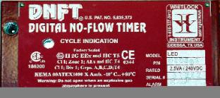
5835372 digital no-flow timer cycle indication instru ins instrument trumen ment t odessa tx usa model. This size breaker requires a minimum of a 10 gauge wire so this wire used would be a 102 with ground. If the water flow is impeded slowed overheated.
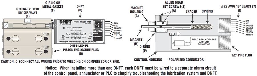
Red - Normally Open No Flow Orange - Normally Closed Flow Black - Common ENTRON defines NC. Plug heater control wire harness to centre wire harness 13 pin 7. The magnet assembly and control.
37 Dnft No Flow Wiring Diagram Pictures. Normally Closed - Attach ohmmeter to orange wires. For larger sizes of pipe use a reducing tee to keep the flow switch close to the pipe and provide adequate paddle length in the flow stream.
Dnft no-flow timer us. The primary components of the maf sensor are thermistor a platinum hot wire and an electronic control circuit. Light for heater controls 2.
F61 flow switch in a standard 1 in. Part of our wiring diagram and electronic series shown here on this channel. Patented sealed magnet assembly.
Trimming Diag ram for the Large Flow Paddle 6 in. The Proflo Jr. Air flow switch wiring diagram.
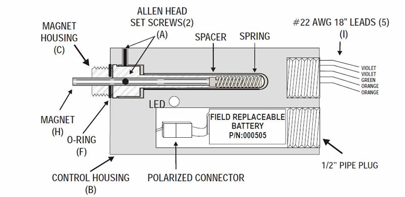
The DNFT-LED is a totally enclosed electronic device combining the latest technology in microprocessor and transistor components for detecting Slow-Flow and No-Flow of divider block lubrication systems. The DNFT is a totally enclosed solid state electronic device for detecting Slow-Flow and No-Flow on in-line progressive lubrication systems. The DNFT incorporates an oscillating crystal to accurately monitor the cycle time of the lubrication system to enable precision timed shutdown capability.
Pipe Original Length FIGpddl_tmplt Table 2.
Https Www Arielcorp Com Content Dam Ariel Corp Documents Pras No Flow Devices Pdf Coredownload Pdf
Dnft Prg P N 000518 Digital No Flow Timer Dnft Digital No Flow Timer For Compressor Lube Systems Whitlock Instrument Dnft Whitlock Noflo Whitlock Instrument Dnft 000518 Prg Timer Model Number
Dnft Prg P N 000518 Digital No Flow Timer Dnft Digital No Flow Timer For Compressor Lube Systems Whitlock Instrument Dnft Whitlock Noflo Whitlock Instrument Dnft 000518 Prg Timer Model Number

Ariel Corporation Arielcorp Com
Dnft Prg P N 000518 Digital No Flow Timer Dnft Digital No Flow Timer For Compressor Lube Systems Whitlock Instrument Dnft Whitlock Noflo Whitlock Instrument Dnft 000518 Prg Timer Model Number
Http Www Truerocksupply Com Filedownload Download File Content Tr01 Downloadcenter Documents Cn 2005 009 20dnft 20magnet 20assemblies Pdf
Whitlock Instrument
No Flow Dnft 2 Min Valve Electrical Connector

Dnft Led P N 000507 P N 000507 Dnft Led Ps Digital No Flow Timer With Dedicated Proximity Switch Install On Dropsa Lincoln Sbco Lubriquip Divider Block Switch Rating 2 5va 240vdc Dnft Led P N 000506 Dnft Prg P N 000518 Digital No Flow

Dnft Led P N 000507 P N 000507 Dnft Led Ps Digital No Flow Timer With Dedicated Proximity Switch Install On Dropsa Lincoln Sbco Lubriquip Divider Block Switch Rating 2 5va 240vdc Dnft Led P N 000506 Dnft Prg P N 000518 Digital No Flow
Whitlock Instrument

Ariel Corporation Arielcorp Com
Whitlock Instrument

Ariel Corporation Arielcorp Com

Ariel Corporation Arielcorp Com

Whitlock Dnft 2 Pdf Document

Ariel Corporation Arielcorp Com
Whitlock Instrument
Whitlock Instrument
Posting Komentar untuk "Dnft No-flow Wiring Diagram"