Danfoss 077f1555 Wiring Diagram
Wiring diagram of the danfoss inverter vlt automationdrive fc 301 302 quick guide wittur lift drive wld operating 0 25 75kw overload protection isave 21 manual espaol conversor de frequncia for marine winch decentral fcd 6000 hvac 8000 aqua low harmonic 132 630 kw blog incontrol 5000 instruction 300 w fc300manual 12. Typical wiring diagram for any LX Thermostat with contactors.

Wiring Diagram For 220 Volt Single Phase Motor Http Bookingritzcarlton Info Wiring Diagram For 220 V Ac Capacitor Electrical Circuit Diagram Circuit Diagram
Wiring Diagram for RMT230 RMT230 230V supply 4 1 3 2 RP RMT230 24 3051 1201 T N COM OFF ON.
Danfoss 077f1555 wiring diagram. Basic Bypass Circuit 1-3 Figure 21. Outdoor datasheets manuals and diagrams. TX-FH Cable installation manual.
Sample Panel Label 2-1 Figure 31. Wiring Diagram DHP-R Danfoss Heat Pumps Box 950 671 29 ARVIKA Phone 46 570 81300 E-mail. Detailed tests that must be performed before start-up.
Hi I had a faulty actuator which I have now replaced however I have lost the original wiring diagram that I made when removing the old unitApr 05 Wiring. Basic Non Bypass Circuit 1-2 Figure 12. TX thermal storage datasheets.
Ripple 5 Current consumption 80 mA Max. I would fit a Honeywell and require back to the main wiring center. Af8a997 wiring diagram for danfoss thermostat.
Load Two parallel connected PVEs. No separate transformer needed. Do not show this message again.
Danfoss Central Heating Wiring Diagrams For more information see the Danfoss Wiring GuideThis video covers the wiring and electrical operation of an S plan system with two 2-port valves. Control terminal functions. The Service Thermostats have a wider.
2-wire loop powered. Climate Solutions for cooling. Wiring diagrams and further information continues below.
Quick wiring overview from test setup. The thermally managed enclosure extends drive lifetime and ensures trouble-free operation. Danfoss Vlt Automationdrive Fc 302 301 User Guide Manualzz.
TX installation manuals and guides. Diagram wiring diagram for danfoss thermostat full version hd quality danfoss thermostat. The English language is used for the original instructions.
Level and setting readout. Megavolt Jan 20 danfoss hsa3 wiring diagram. Diagram wiring diagram for danfoss thermostat full version hd quality danfoss thermostat.
The enclosures which feature lifting lugs. Other languages are a translation of the original instructions. The enclosed VACON NXC is the compact drive that performs reliably in harsh operating conditions in for example the mining oil and gas or water and wastewater industries.
Danfoss reserves the right to alter its products without notice. TX-SH Cable installation manual. Initial programming to verify proper functioning of the drive system.
The installation guide is intended for use by qualified personnel. Kic fridge freezer thermostat. AKS 41004100U can be connected directly to Danfoss EKE 347 liquid level controller and thus be powered from EKE 347.
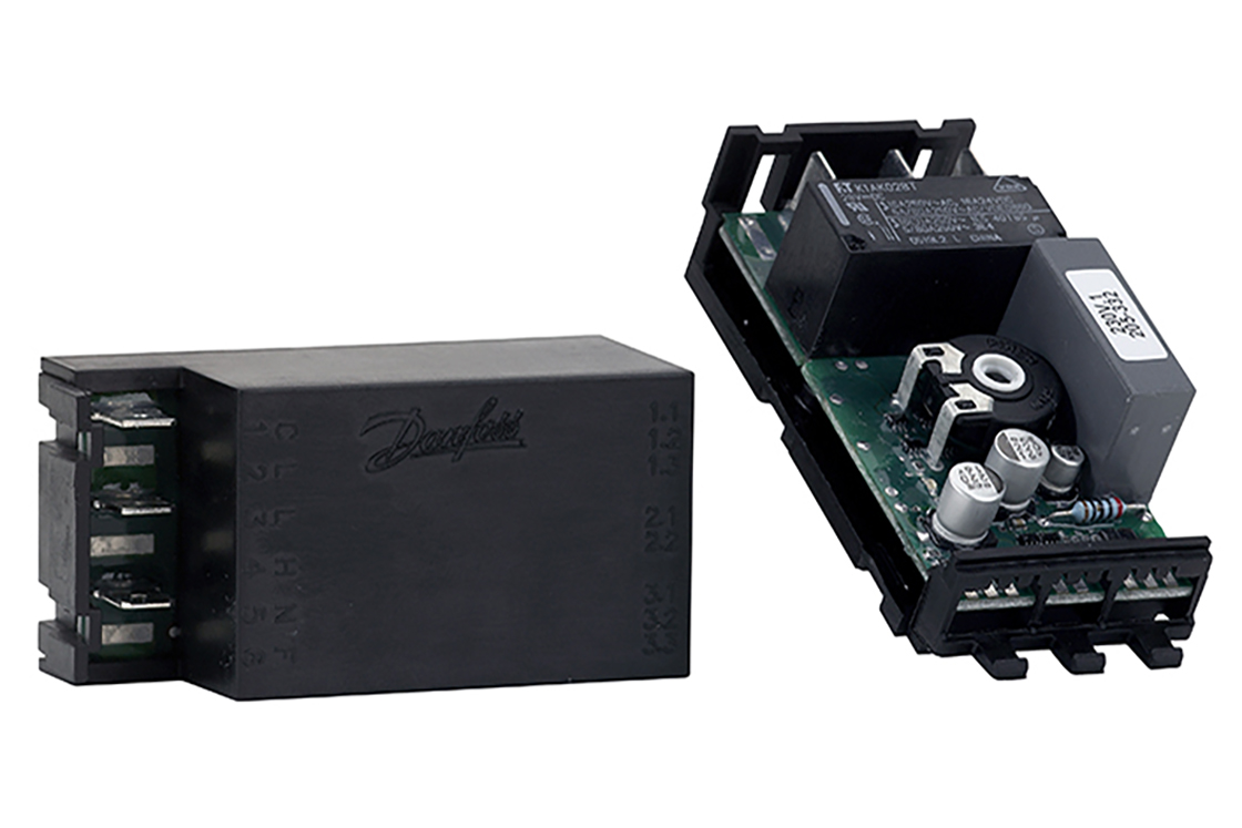
USA Product Store Continue to Global Catalog. Follow our global channels Keep me updated. This diagram shows the wiring layout using the most typical components.
Side Cooling Clearance 3-6 Figure 33. Here coloured wires indicate. Eight Danfoss service packs are enough for thermostat servicing on all types of refrigeration and freezing appliances and make spare parts catalogues cross reference lists and temperature tables unnecessary.
44 Wiring Schematic 14 45 Access 15 46 Motor Connection 15 47 AC Line Input Connection 31 48 Control Wiring 31 481 Control Terminal Types 31 482 Wiring to Control Terminals 33 483 Enabling Motor Operation Terminal 27 33 484 VoltageCurrent Input Selection Switches 33 485 Safe Torque Off STO 34 486 RS485 Serial Communication 34 49 Installation Check List 35 5. How to do wiring and testing of Danfoss oil pressure switchin airconditioning and refrigeration system. Wiring of mains and motor connections.
812 Mechanical Diagrams 9-2 813 Typical Wiring Diagrams 9-6 Contents Vertical BypassNon Bypass Panel MG13A122 - VLT is a registered Danfoss trademark. This also applies to products already on order provided that such alterations. Force 50 N 1124 lbf Output voltage US US 025 075 UDC Neutral voltage US US 05 UDC Output signal Max.
Proper Lifting Method 3-5 Figure 32. FPSi Electronic 2-Channel Full Programmer for Heating and Hot Water with Service Interval Timer Danfoss Heating. If used together with Danfoss EKC 347 liquid level controller a 14 30 V DC supply is required.
If you are looking for Danfoss USA Product Store and catalog - which enables you to purchase our products - then please select the USA Product Store button. RX roof deicing datasheets. Wiring of control and serial communications.
Multi language HMI. About Danfoss Careers Contact us Home page. Double door fridge thermostat.
The Service Thermostats and the necessary accessories are contained in practical boxes complete with electrical diagram and drawings of contents. Contents Figure Figure 11. Flexible robust and serviceable.
Technical data Supply voltage UDC 11- 30 UDC Max. Wiring diagram for danfoss thermostat.

Danfoss Relay Oil And Capacitor Type Connection With Diagram In Urdu Hindi Fully4world Refrigeration And Air Conditioning Capacitor Hvac Air Conditioning

Danfoss Relay Oil And Capacitor Type Connection With Diagram In Ur Air Conditioning System Design Refrigeration And Air Conditioning Electrical Circuit Diagram

09132211861 Circuit Diagram Control Board Wiring Power Diagram Inverter Ac Repair

Central Heating Wiring Diagrams Danfoss 3 Port Mid Position Wireless Stats Gas Support Services

Domestic Refrigerator Starting Relays Refrigerator Compressor Refrigeration And Air Conditioning Electrical Circuit Diagram

602 602shares Diagram Connection Watch Video Practical 7 699 Total Vi Refrigeration And Air Conditioning Basic Electronic Circuits Basic Electrical Wiring

Danfoss Bd35f Compressor Service Manual
Eet Electronic Thermostats Danfoss

Unique Wiring Diagram For A Central Heating System Diagram Diagramtemplate Diagramsample Heating Systems Underfloor Heating Central Heating System

Danfoss Wiring Diagram Central Heating Diagram Diagramtemplate Diagramsample Check More At Https Servisi Co Danfoss Wiring Diagram Central Heating

Wiring Diagram For 220 Volt Air Compressor Http Bookingritzcarlton Info Wiring Diagram For Refrigeration And Air Conditioning Hvac Air Conditioning Hvac Air
Electronic Thermostat Control Etc 1h3 Electronic Thermostats Temperature Control Electronic Controls Climate Solutions For Cooling Danfoss Global Product Store

55 New Potential Relay Wiring Diagram A Govern Relay Is Used In The Automotive Indu Electrical Circuit Diagram Electrical Wiring Diagram Hvac Air Conditioning

Electronic Thermostat Control Etc 1h3 Electronic Thermostats Temperature Control Electronic Controls Climate Solutions For Cooling Danfoss Global Product Store

Diagram Kenmore Pressor Wiring Diagram Full Version Hd Air Conditioner Maintenance Electronic Parts Electrical Installation

45 Beautiful Danfoss Compressor Relay Wiring Diagram Compressor Air Conditioner Maintenance Relay
Electronic Thermostat Control Etc 1h3 Electronic Thermostats Temperature Control Electronic Controls Climate Solutions For Cooling Danfoss Global Product Store

Pin On House

Pin By Juan Torres On Cooling Refrigeration And Air Conditioning Hvac Air Conditioning Air Compressor Repair
Posting Komentar untuk "Danfoss 077f1555 Wiring Diagram"